| Home | Project | Parts | Contact us |
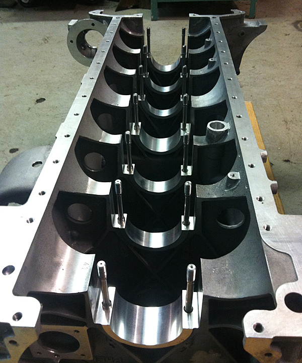
The months from July to October have little pictorial evidence to explain the amount of detailed work that has taken place. After completing the first phase of operations on the 5-axis machine it was necessary to undertake a full dimensional analysis of the first block to ensure axes, angles and face positions were all accurate prior to the final surface cuts. This photograph shows the underside of the block, main bearing studs in position, ready to accept the machined caps. |
 |
| Viewed from the flywheel end this shows the finished main bearing caps in position. The gap between the block and cap is where the 0.125" spacers fit, which control the nip on the bearing shells. | 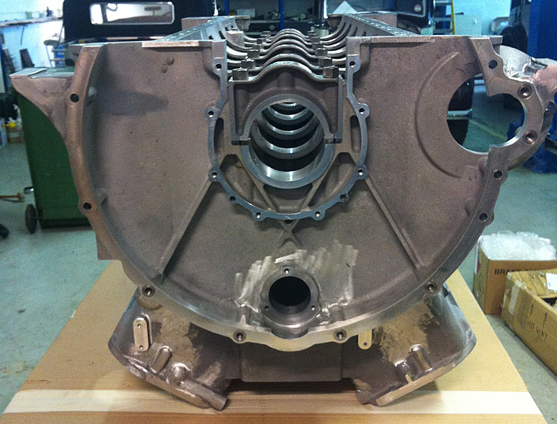 |
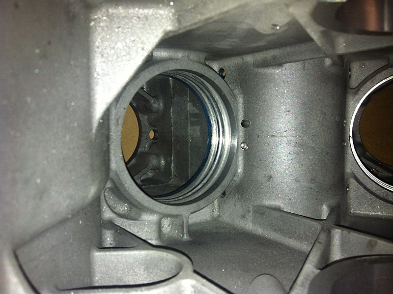
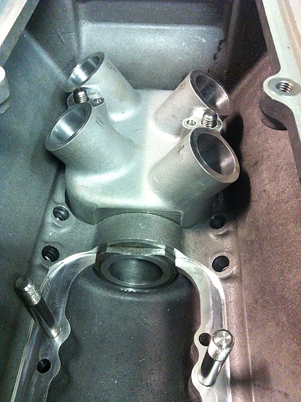
Looking upwards from the crankshaft area, this shot highlights the quality of the bare casting surface inside the block. The main orifice in this picture, which carries one of the cylinder liners, has three annular grooves: the upper and lower ones carry sealing 'O' rings for water and oil, respectively, with the centre groove being vented to the outside. Visible through the orifice is the underside of the fire face where the upper lip of the wet liner is seated. |
 |
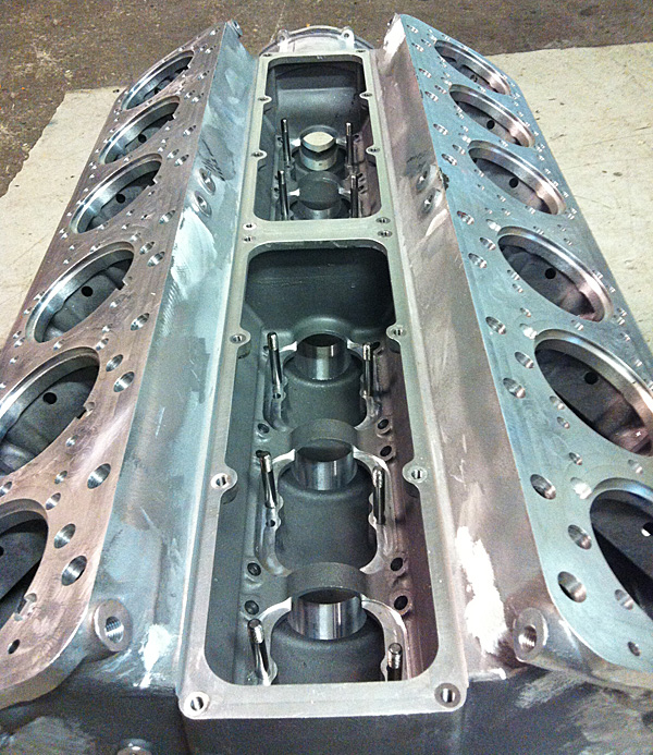
5-axis work completed and prepared for line boring of the crank and cam shaft bearing housings. The block outer surfaces are yet to be fettled to finished standard. The studs for the tappet follower blocks are installed but the tapered locating dowels will be left for the engine builder to fit. |
 |
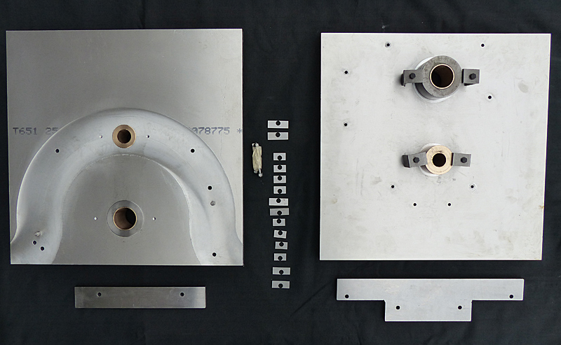
Preparation for line boring the crankshaft and camshaft bearing housings. These jigs are for the rear and front of the block showing the 14 slave spacers to be used under the main bearing caps during the boring operation. The datum for all alignments is the lower block face. The axis positions for the crank and cam are critical for ensuring everything fits and works after assembly. The jig positions are accurately machined to ensure the axes are maintained during the boring procedures |
 |
One of the numerous trial fitting tests made after the machine work had been completed. This picture shows the number 1 tappet follower block and cam bearing in position. Interestingly, this is a non-standard tappet block that is made to a post-war design for carrying rotating tappets.
|
 |
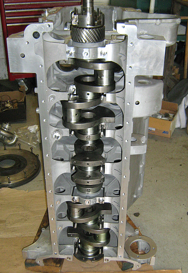
Trial fitting a crankshaft using only two main caps and old bearing shells, at this stage, as the new shells will have to be line bored to fit the engine's correct crankshaft. The purpose of this exercise is to ensure the accuracy of journal positioning relative to the block walls, bore centres and related gearing. At the top of the photograph, attached to the nose of the crankshaft, is the pinion and lugs that carry the crankshaft damper. End float of the crankshaft is governed by a thrust face machined onto the forward face of the number 7 main bearing so can only be set up during the final shell boring process. |
 |
| Test fit of a flywheel onto the slave crankshaft to confirm clearance distances from the block body plus accurate engagement positioning with the starter motor pinion. | 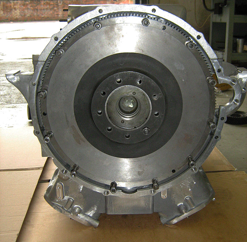 |
| Further physical testing of components. This shows the cam wheel, crankshaft damper, idler gear and dynamo drive all engaged and aligned. Final backlash adjustments will be made during assembly. The idler gear has a movable spindle plinth that, once correctly positioned, is dowelled and bolted into the block. The dynamo drive backlash is adjusted using an eccentric support ring located around its bush: the output being via a floating shaft running through the centre of the pinion. | 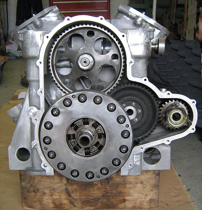 |
| This timing cover is the unit to be fitted to this block and it can be seen that the edge alignment is spot-on. The pulley, fitted to the nose of the crankshaft damper, not the crankshaft itself, must clear the annular oil scroll by 0.008". It is a pleasure to report that everything is concentric. | 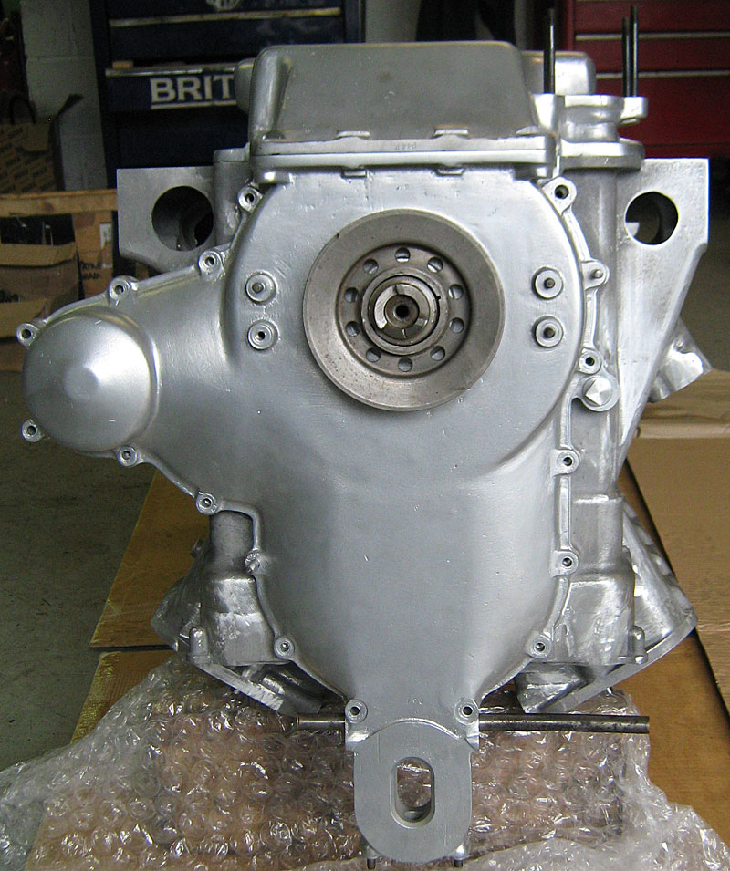 |
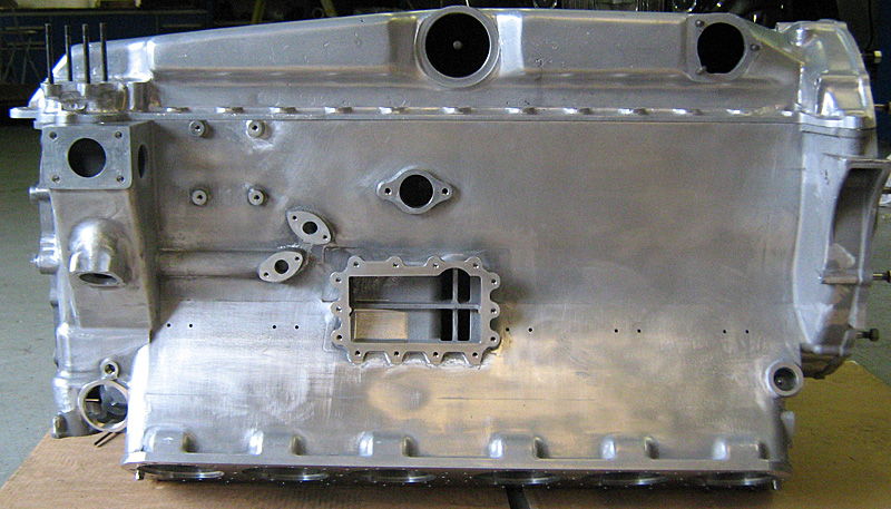
So here it is! Delivered to its new owner on Friday, 4th October. The first block off the line showing the sump pan that it will carry when finally assembled. Preliminary fettling of the exterior shows an excellent surface match to the original sump and other closing panels. The remaining blocks are being passed through the machining stages and incorporate all amendments to the CNC procedures that have been identified during the audit and manufacturing processes. It is hoped that this unit will be assembled and run in the very near future. Come back for the movie! |
 |
© Copyright 2011-2015: Phantom Engineering Limited.