| Home | Project | Parts | Click for next page |
The following photographs show how the casting box is assembled from the 45 sand pattern cores. The sand is bonded using a heat resistant resin: the larger patterns are rammed by hand whereas the smaller, delicate ones are 'blown'.
Terminology:
The 'drag' is the base of the core box onto which all of the remaining cores are loaded.
The 'cope' is the lid of the core box, the internal profiles of which create the upper surfaces of the casting.
The 'sprues' are the vents in the top and sides of the core box that allow the molten metal to be poured into and eventually flow out of the box.
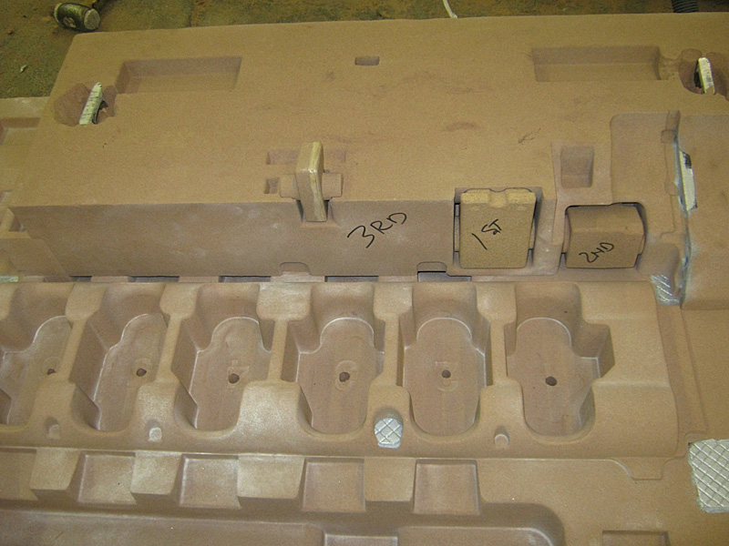
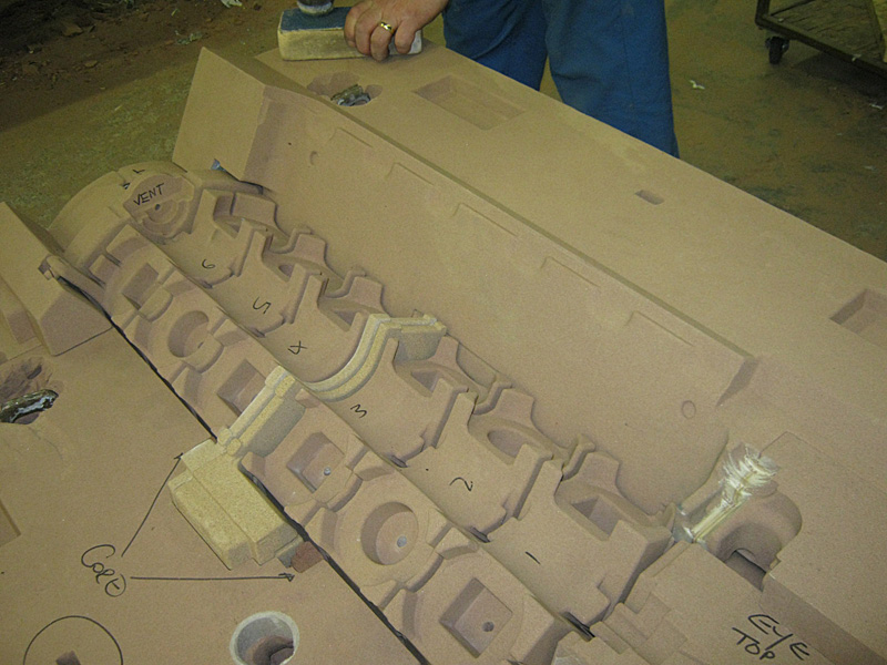
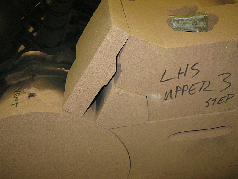
The drag lying with the front of the block to the right. At the top of the picture is the first piece forming the outer, B side (nearside) engine wall. The six sockets are used to locate the six 'cranks' - the cores that form the voids in which the crank throws rotate plus the support webs between each pair. Close inspection of the base of each socket shows the numbers 1 through 6 embossed in the floor. The small core marked "2nd" will form the hollow front, nearside foot for the engine. The piece marked "1st" will create the support saddle for the dynamo. Above and to the left of "3rd" is the first of two pieces that create the saddle for the water pump. Additional photographs appear later on as the box is loaded.
|
 |
| What appears to be vandalism is actually improvements to the locating of the 'cranks' to the upper cores that will form the cylinder cavities and upper block decks that mate to the cylinder heads. More will be revealed later. |  |
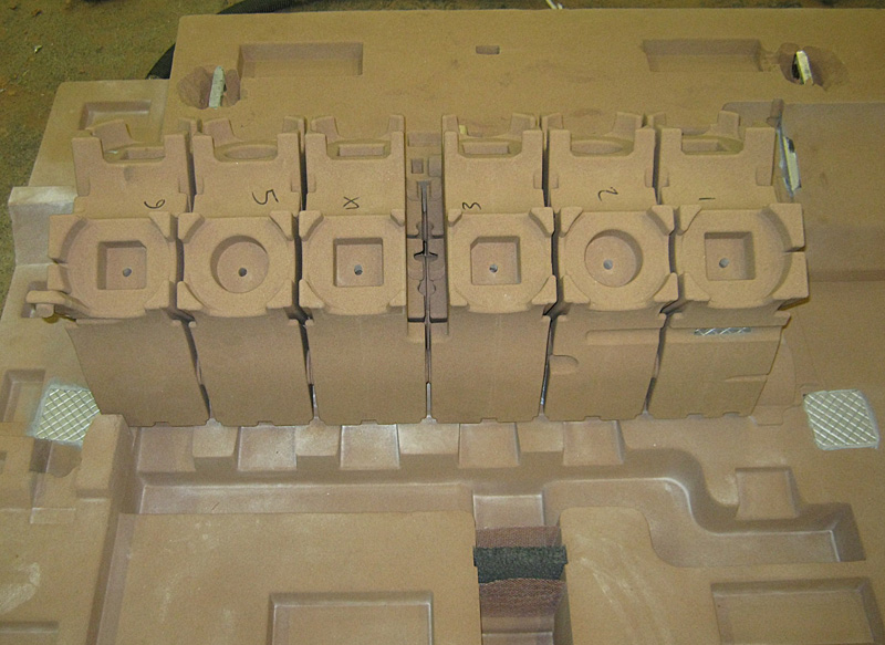
Front to the right and viewed from the A side (off side): the six 'cranks' have been installed in the cope in preparation for the assembly of the outer walls. Note should be taken of the void between the 3rd and 4th crank pairs that coincides with the water pump inlet on the opposite side. |
 |
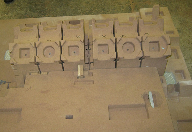
The same state of assembly shown from the other side. The metal insert, bottom right, supports part of one of the lower sprues. |
 |
This is the front end wall lying on its back with the inner surface uppermost. The X bracing is clearly visible above the upper portion of the front main bearing housing. "Don't forget core"!!! The core is the D shaped blob at the top of the photograph that will, once in place, create the hole through the front wall that where the idler gear spindle will live. |
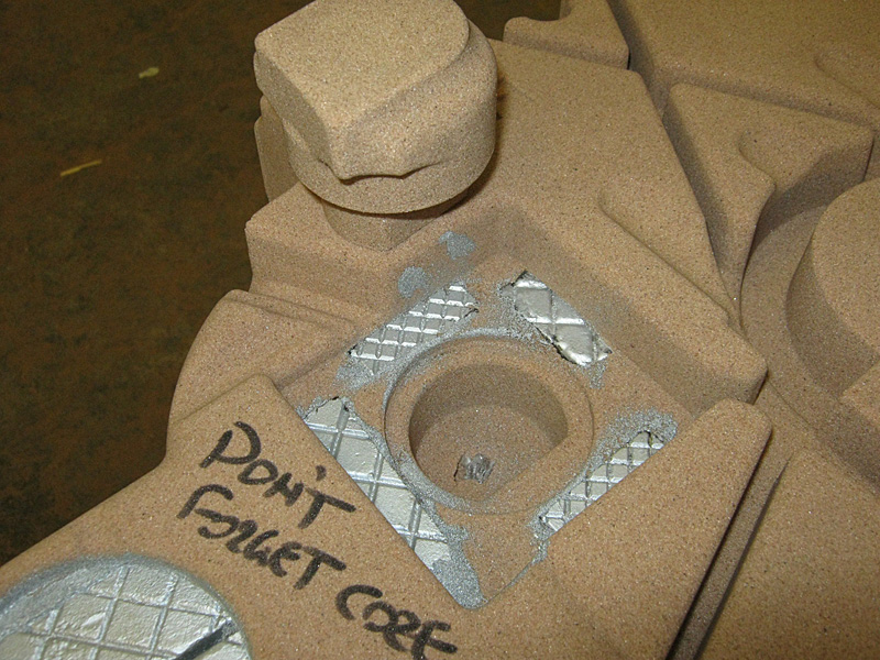 |
| Such relief! Somebody remembered to fit it. | 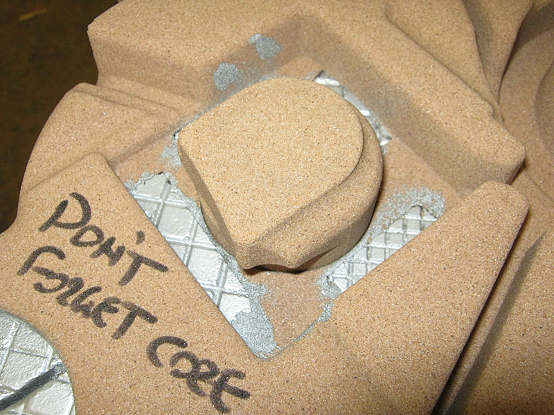 |
One of the numerous small cores needed to allow easy assembly of the whole. |
 |
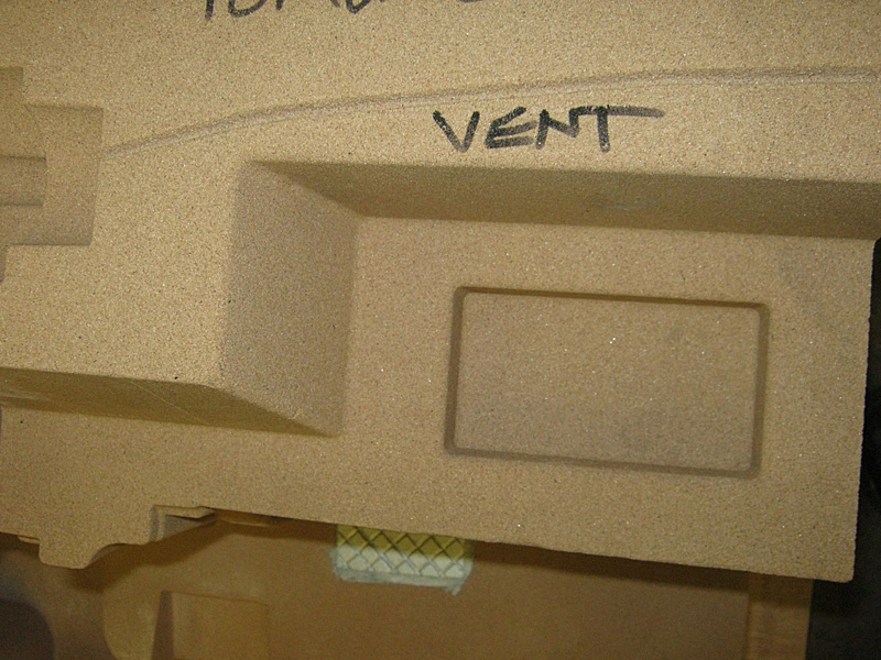
| One of the outer, lower cores forming the front timing or gear chest. |  |
The same piece as above now carrying an air vent. The square socket is to accurately locate the next piece if the jigsaw. |
 |
Showing how complicated the construction becomes due to the convoluted nature of some of the walls. The dark coloured core has to be slid into its cavity after the main parts have been installed. |
 |
| This shows a small air vent inserted in the core that created the forward face at the back of the timing cover. The half moon shape accepts the end of the core that creates the camshaft aperture, which will be seen on part of the cope assembly towards the end of the page. | 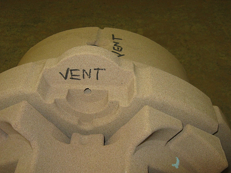 |
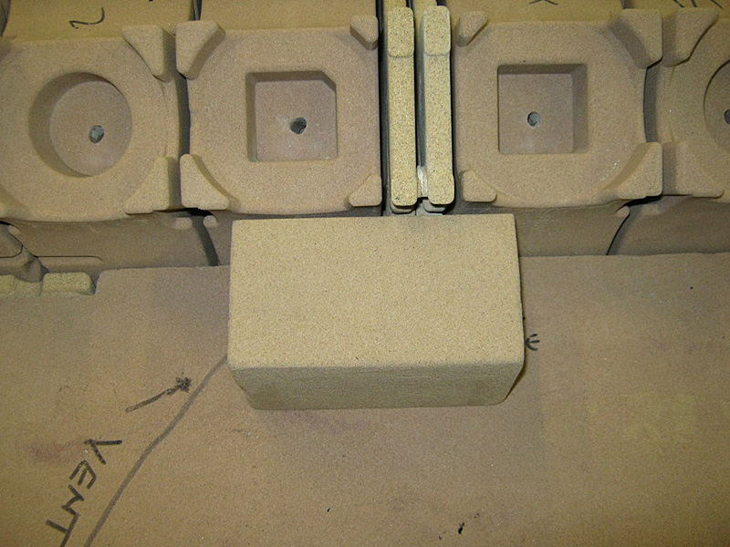
| More cavities created for the sprues. | 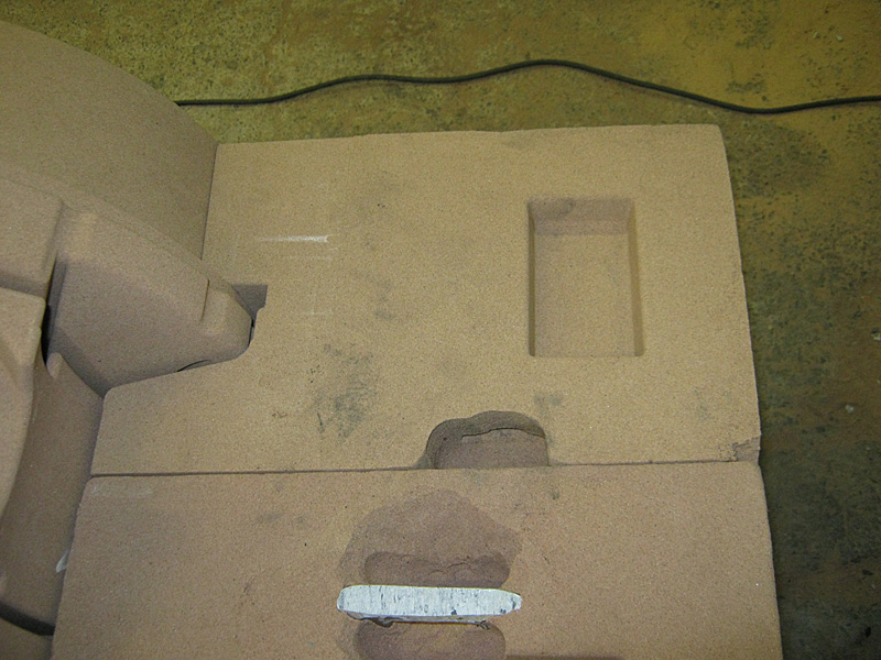 |
Some of the smaller cores need to be glued into place to make sure that do not move as the later pieces are assembled. This one was shown in the first photograph and helps form the saddle for the water pump. |
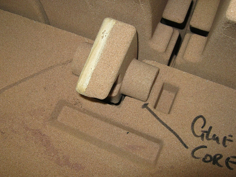 |
The third photograph made mention of a void between cylinder pairs 3 and 4. These two delicate parts create the three walls between which the coolant will be pumped as it enters from the eater pump orifice on the right. Note that the cores are glued at the right hand side to ensure they stay where they are needed. Post production it will be necessary to inspect these walls both visually and by x-ray. |
 |
See two pictures back - the vent onto the water pump saddle. This part really created some problems. |
 |
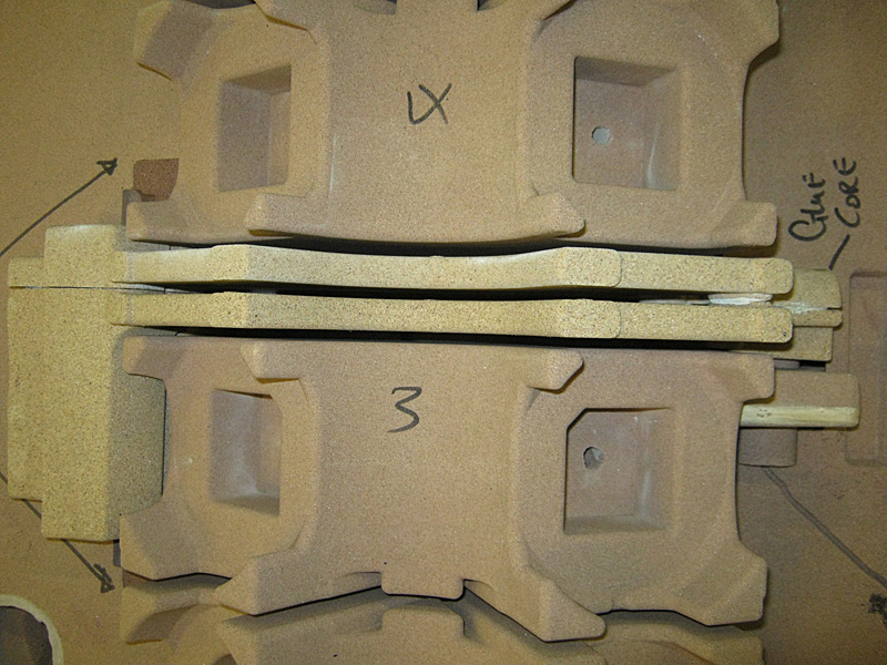
The final part of the water pump saddle installed and vented. This shot demonstrates clearly how the nearside, outer wall will be formed in the narrow cavity between all of the cores. The webs between each of the cranks will end up at 1/4" thick. Worthy of note are the different socket shapes in the top of each 'crank' to ensure that next pieces are inserted in the correct locations. |
 |
The lower sections of the core box are completed. Final adjustments are being made to ensure a close fit of the mating faces by sanding the sand... |
 |
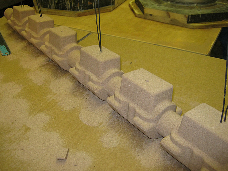
| The first set of upper cylinder cores being fitted. Number 6 has to be attached to the cope to allow all of the sections to slide together. | 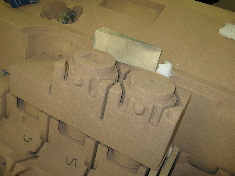 |
| The small wooden and foam wedges are left in place until the adhesive has set between the upper and lower cores. | 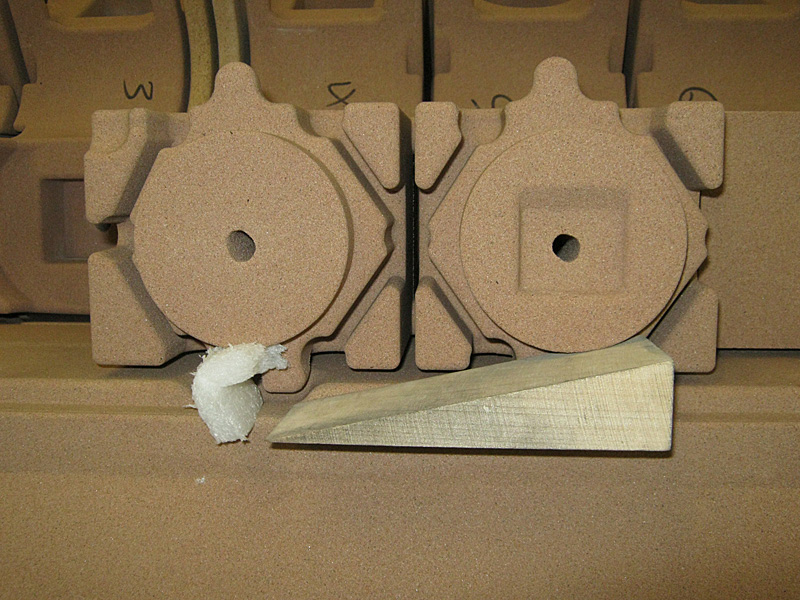 |
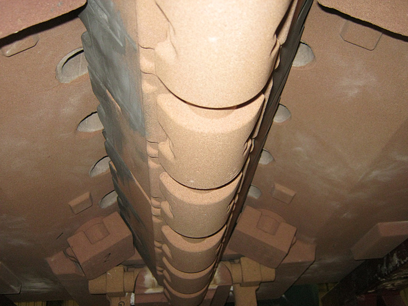
| A view of the underside of the cope prior to installing the complicated cores that form the cam wells and camshaft cavity. The large holes are the sprues for each side of each crank pair. | 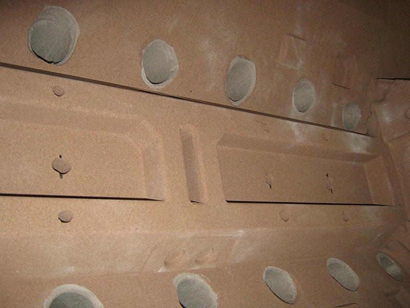 |
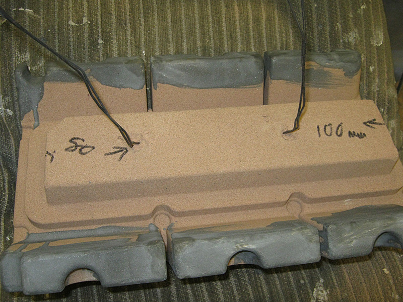
One of the two core pieces that locate into the two sockets shown in the previous photograph. The wires will be passed through the lid of the cope and tied off to ensure these parts to not move. The outer walls will create the shape of the two inner walls of the engine V. |
 |
| The previous part installed in the rear half of the cope. | 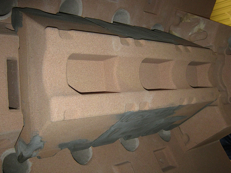 |
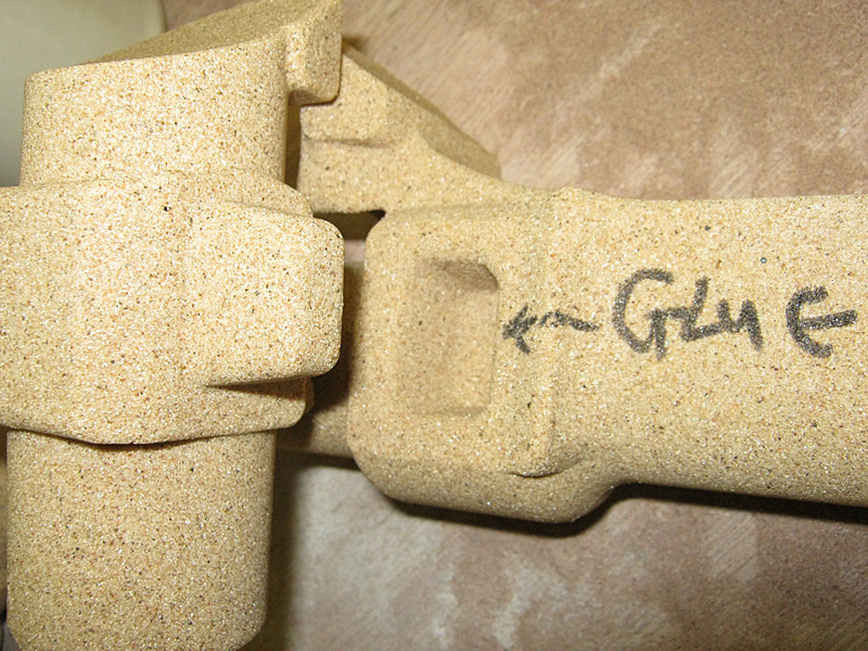
This and the following two photographs show some of the complications in casting this engine. These two pieces are about 5" long. At the front of the engine there are two hollow towers, one on each side, that accept the two ignition distributors. These pieces form the vertical core of the one tower plus the internal oil weir that spills oil onto the timing gears. |
 |
| Glued together and lying on its back. The section lying on the table will stand vertically and the horizontal piece then forms the outer end of the cavity for the front cross-shaft that drives the two distributors and oil pump. | 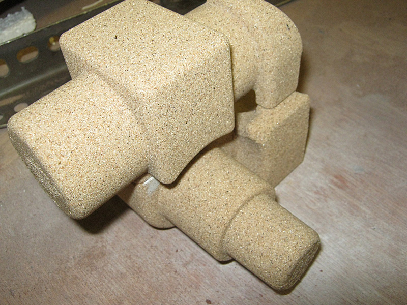 |
| The forward end of the cope with the cross-shaft and distributor tower cores in place. The camshaft would sit in the semi-circular rebate that runs roughly top-to-bottom of the picture. | 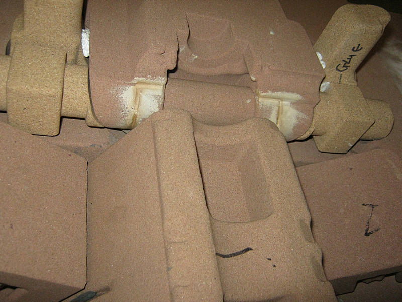 |
This is the blown core that forms the cavity in which the camshaft will sit. The narrow rod sections between each shaped piece will be where the camshaft bearing bridges will be formed during the casting process. Again, the wires are fed through the top of the cope and tied off to prevent the core from moving.
|
 |
The cope, now rotated into its correct orientation, looking towards the front of the engine. The camshaft core is now wired into place and, at the far end, the cross-shaft and distributor tower cores can be seen. At the far end of the cope, either side of the cam well, there are two squarish cores that form the two number 1 cylinder cavities. (See the next shot.) |
 |
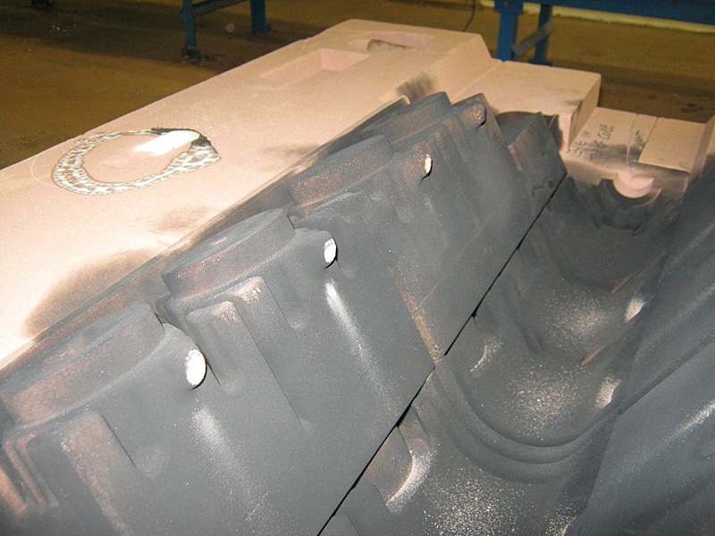
The box waiting for the cope to be installed. The cam wells in the centre of the V and the #s 2, 3, 4 & 5 upper cylinder cores in place on either side of the V. The cores have been sprayed black in a similar fashion to using engineers' blue: the cope will rub against any high spots as it is test fitted. The white nipples needed slightly relieving to avoid knocking the outer cores out of alignment. The sand in the base of the well was blown out before final assembly. |
 |
The odd cores being inserted at the front of the core box before the cope is fitted. Note the sprue hole cut into the top right of the large core. |
 |
| Cope in place, sprue pipes sand-packed and all wire-tied cores tightened with wedges. |  |
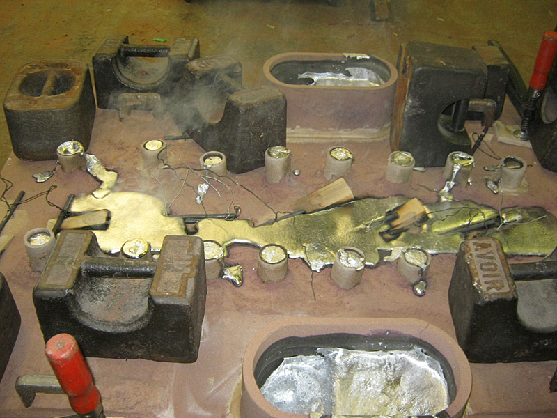
With sufficient weights loaded onto the top of the box to prevent hydraulic lifting during the pour. The molten aluminium alloy was poured simultaneously by two teams into the two funnels. Total pour time was an incredible 30 seconds. |
 |
| Left to rest... | 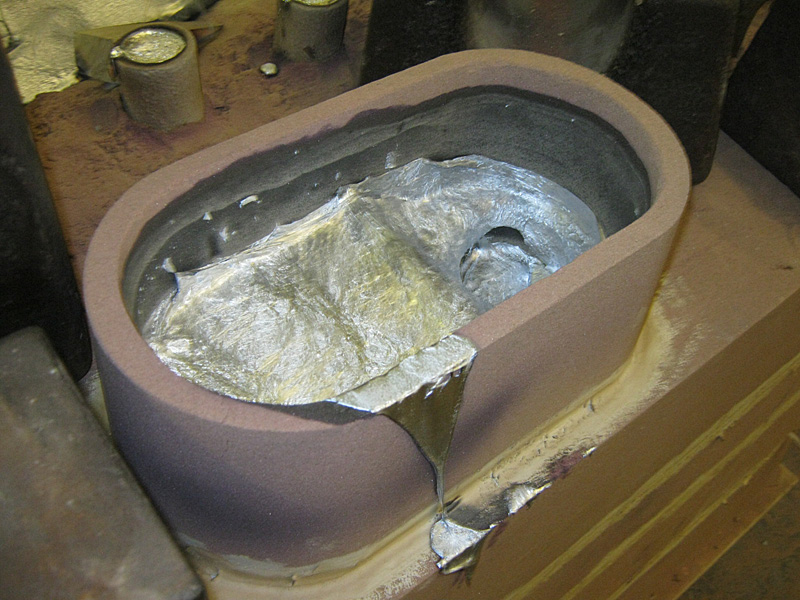 |
© Copyright 2011-2015: Phantom Engineering Limited.