| Home | Project | Parts | Click for next page |
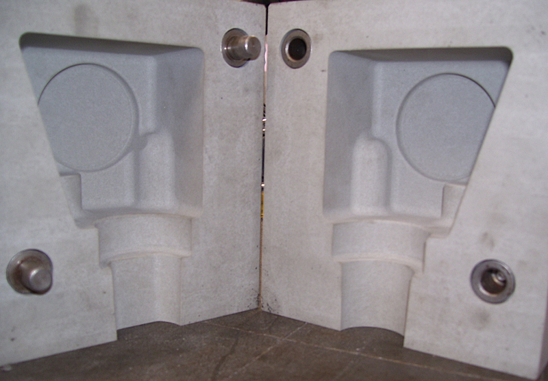
The following photographs show the tools in which the casting sand is moulded to make to cores. The two halves of each tool are accurately located by metal plugs and sockets. Each sand core has a uniquely shaped lug or countersink to prevent assembly in the incorrect position. Some of the more complex designs have additional small tool pieces inside that create internal voids that would otherwise be impossible to unpack when splitting to tool halves.
| This CAD image shows the tool for generating one of the 'V' cavities for a pair of cylinders. The sand core is represented by the purple piece: the five small coloured insert tools create undercuts and internal voids in the core. The latter pieces have to be extracted from the sand core after the main tool box has been split. | 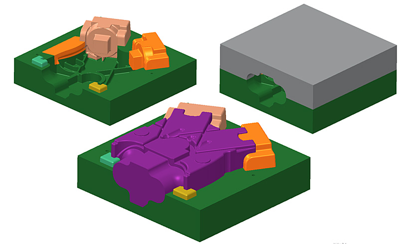 |
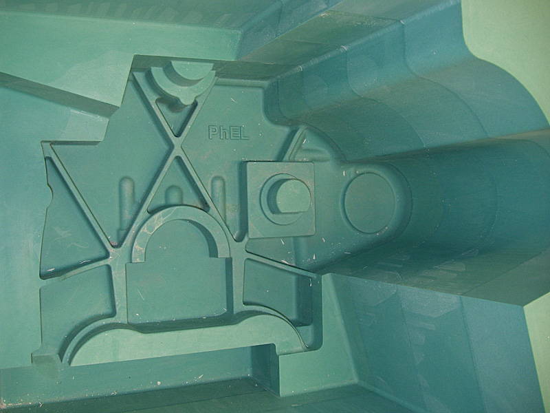
| As shown in the previous image: this is the finished tool for number 3 cylinder core. The two major insert pieces can be seen in the lower half of the tool. The tools to the left and right of the centre piece are for cores number 4 and 1, respectively, as can be seen by the machined number in the body of the pattern. | 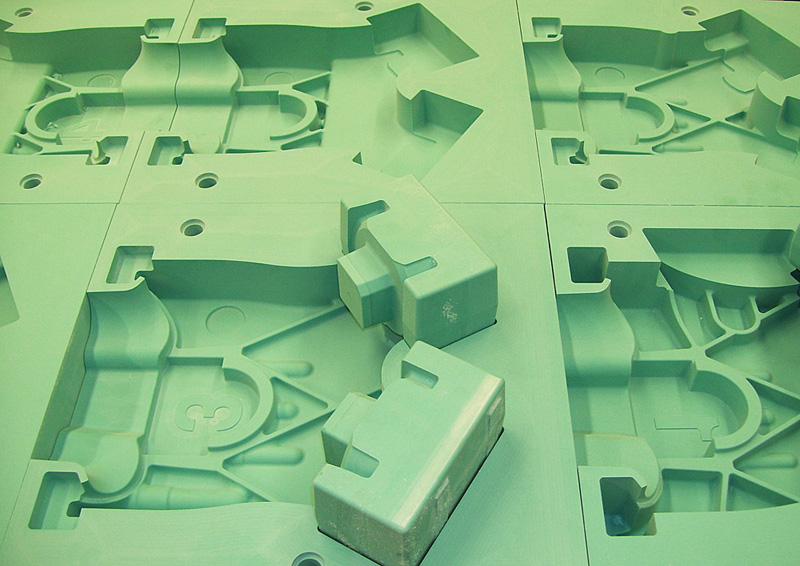 |
| One of the more complicated small tools. | 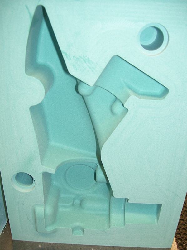 |
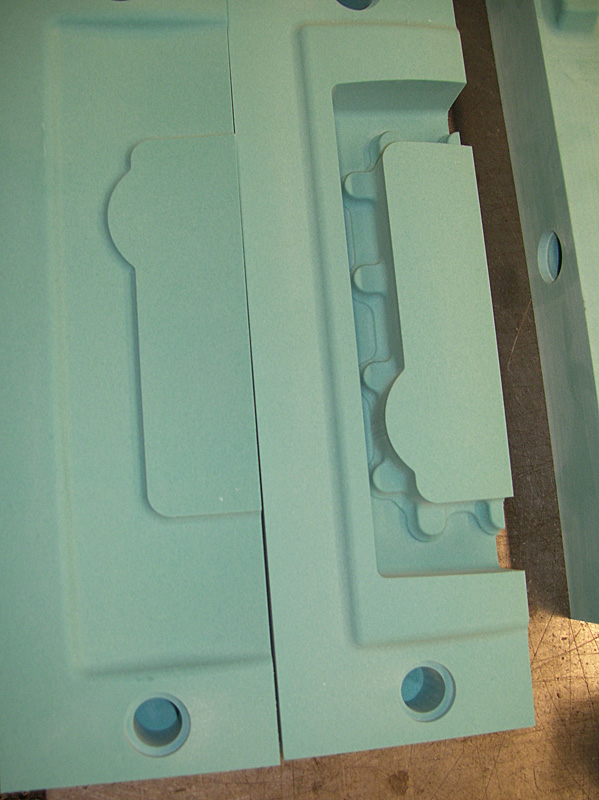
This pair form the core for the dynamo saddle. |
 |
 |
|
| This is a photograph of the 'drag' being machined. The drag is the base section of the mould pack onto which all of the upper tools are located. | 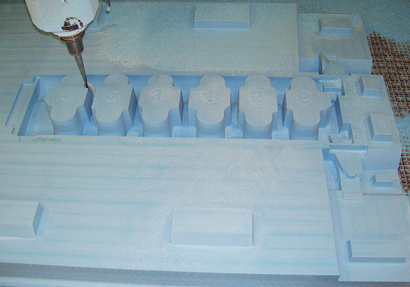 |
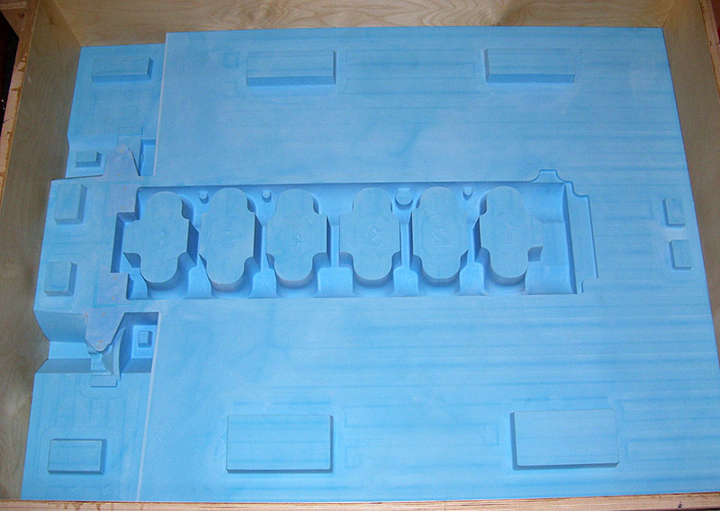
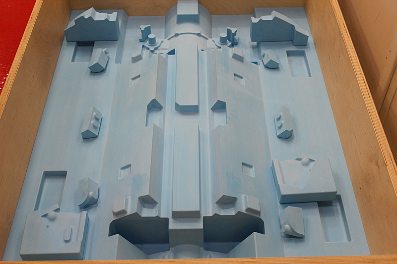
The drag completed and being tried for size in the casting box. In this and the previous image one can see the numbers 1 to 6 for the 6 cylinder void pairs. |
 |
| The tool set for creating the flywheel case at the rear of the engine block. | 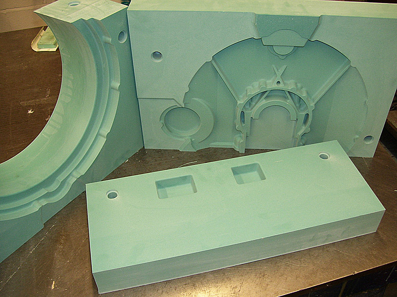 |
| The flywheel case tools shown assembled but without the end closing piece. | 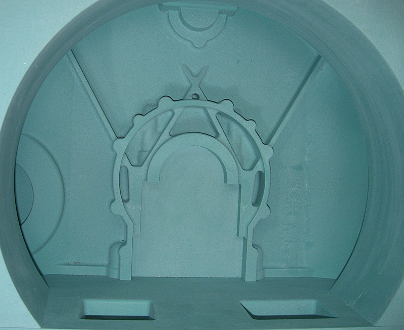 |
This is a loose piece of tooling that attaches to the offside wall of the engine block to form the return flange for mounting the oil cooler blanking plate. |
 |
| Another detail piece that will form a rear foot at the base of the block. | 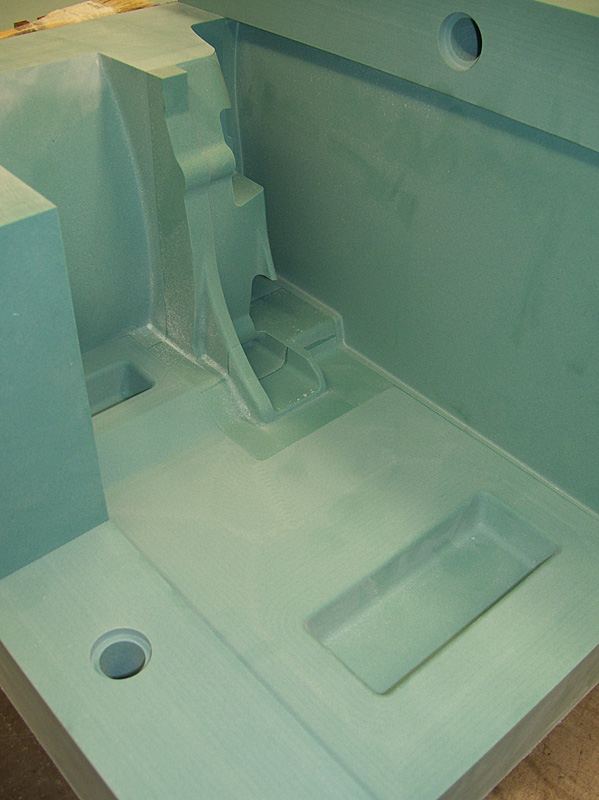 |
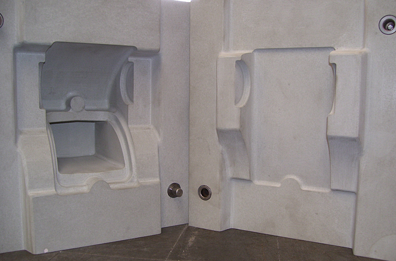
| This shot is looking along what would be the nearside, lower edge of the block – front on the left. From left to right the tooling creates: - – inner element of the nearside front engine foot – the hollow saddle that will support the dynamo – the lower half of the water pump support saddle. |
 |
The front wall of the timing chest at the front of the engine. Further loose pieces will slot onto this vertical wall to produce the complicated outlines of the oil weirs, gear platforms, cross-shaft and camshaft bearing block. |
 |
| One of the small loose pieces that demonstrates how the cores are packed and formed. | 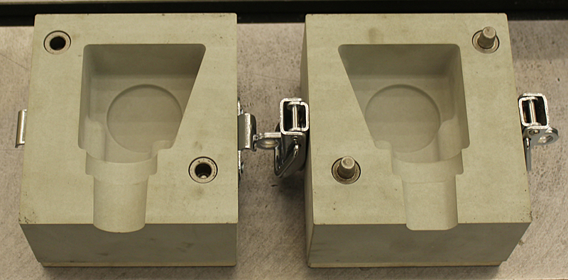 |
The cope - this is the lid that closes the casting box. Shown here lying upside down and holding 10 of the 12 loose pieces that are necessary to enable the mould to be lifted out of the box after packing. The front of the block is at the top of the photograph. The two rectangular upstands (top to bottom centre in the picture) form the apertures for the two cam chests and the two long angled profiles provide the inner side walls to the cylinder banks. |
 |
| Another of the small pieces: this one will generate the core that forms the nearside rear foot. Note the tiny element at the front that fits into the marked gap on the base of the main tool. This removable part is necessary to allow extraction of the tool from the moulded sand without damaging the core. | 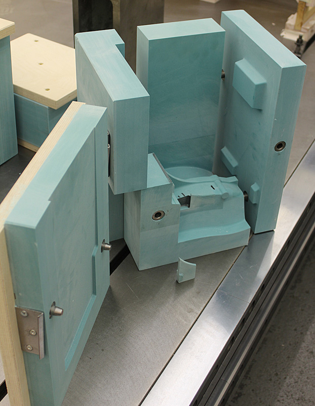 |
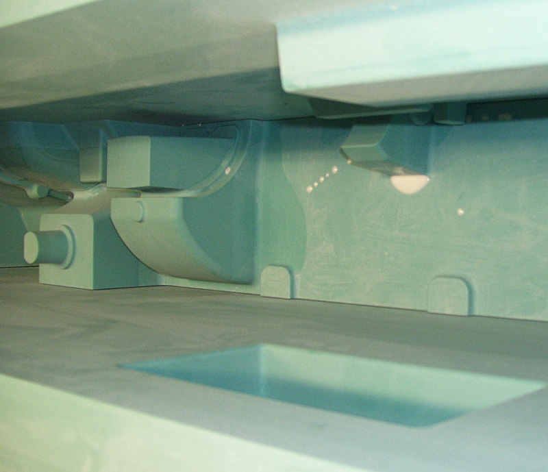
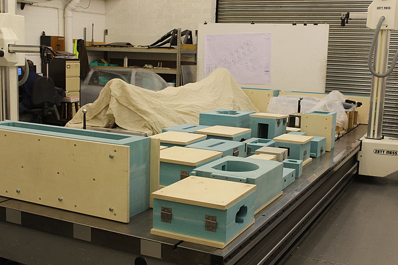
That's it! All of the tooling is finished and, shown here, is half of the tooling assemblies - the other half being stored in the next room. Altogether there are 45 sub-assemblies for the whole project. Each sub-assembly can contain up to 14 separate parts that go to make the core piece. |
 |
© Copyright 2011-2015: Phantom Engineering Limited.