| Home | Project | Parts | Click for next page |
After the successful audit of the CAD design for the engine block the project has moved on to its second phase of designing and manufacturing the numerous mould tools.
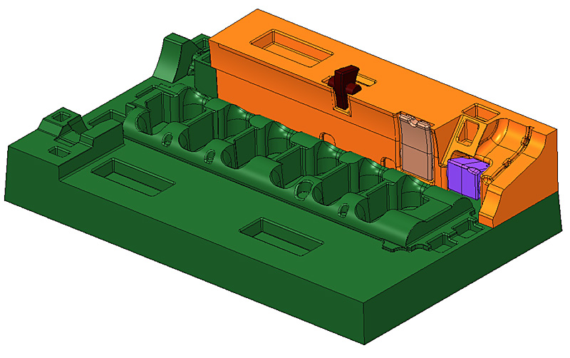
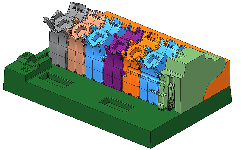
The following images show a step-by-step development of the tooling mould pack and how the cores fit together inside the casting box to provide the voids into which the molten alloy will be poured. Each segment is identified by a colour or number, the interfaces are all different shapes and sizes to prevent incorrect assembly and the parts are tapered to ensure that they can be accurately assembled. The whole 'negative image' of the block will eventually be created in casting sand and the process repeated for each block cast.
The 'drag' or base of the tool pack showing the locating sockets for the different core pieces. The front of the engine block is on the right hand side in this set of images. |
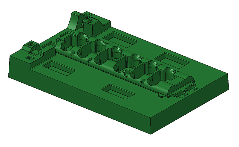 |
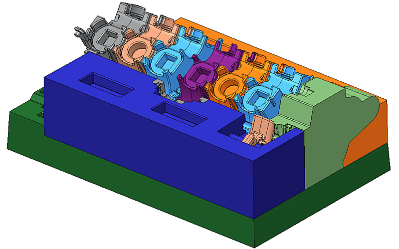
| The nearside core that provides the outside wall of the lower block area.
Three smaller cores are installed in the main piece to provide the following: - brown - exterior saddle for the water pump support fawn - dynamo support purple - front engine mounting foot. |
|
| The six centre cores that will produce the lateral support webs, upper main bearing housings and the floor for the water gallery. It will be noted that the upper locating sockets are all of slightly different shapes to prevent incorrect assembly of the upper cores. The thin horizontal half-cylinder rebate across cores #1 and #2 (darker blue and orange) will produce the body through which the timing chest oil supply will be drilled. | 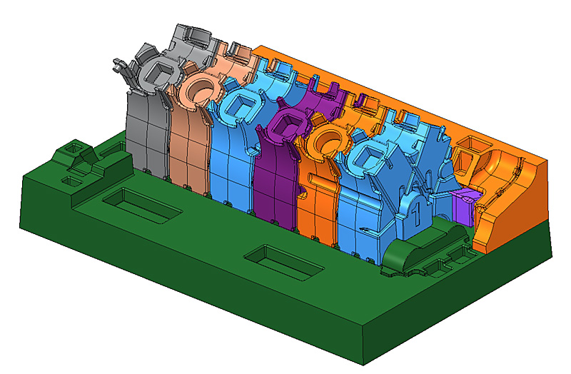 |
Next installation, just visible in fawn behind the front core, are the pieces that will provide the remainder of the floor for the water gallery. |
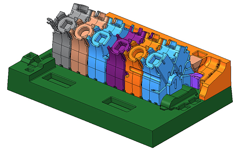 |
The lower half of the engine block front wall is created by this piece. The inner face creates the various lands that will support the timing gear spindle housings. |
 |
The offside core is added to form the lower wall of the block. |
 |
| The insertion of the rear core will provide the back wall of the block as well as the inner profile of the flywheel and clutch housing. At top centre of this core can be seen the lower half of the camshaft rear bearing housing. With the front and rear cores in place, lined up with the six cores that will create the con rod cavities, the upper 'V' between the two sides will form the base of the central camshaft well. | 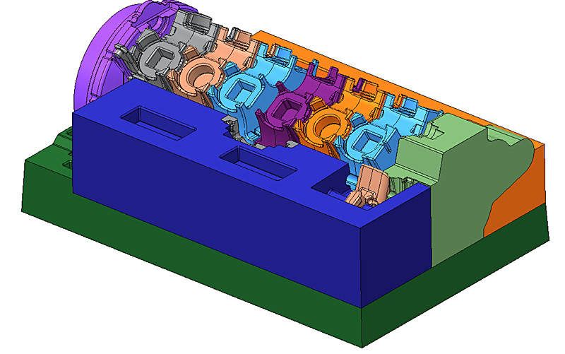 |
| Completing the lower half of the block is the small core at the rear offside corner. | 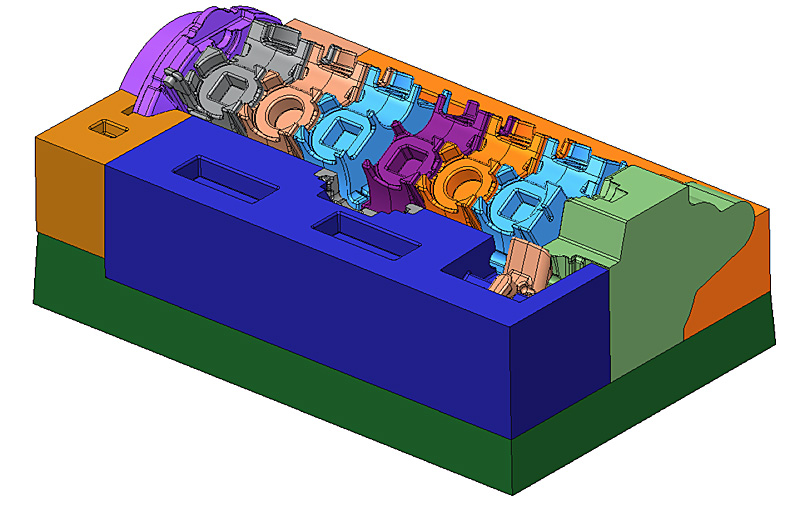 |
| Inserted between the numbers 3 and 4 cylinder cores are the complicated pieces that will create passageways for front and rear water supplies. The additional former on the offside will create the external housing for the redundant oil cooler. This latter part was deleted during the production run, being removed in-service from existing engines, and the exterior aperture closed off with a blanking plate. | 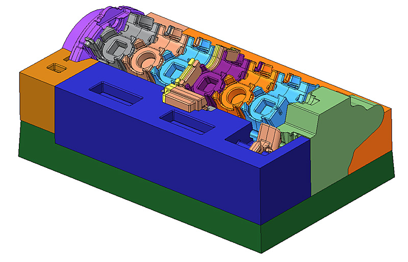 |
| The small core fitted on the nearside of the block will create the inlet passageways to the water gallery from the water pump. | 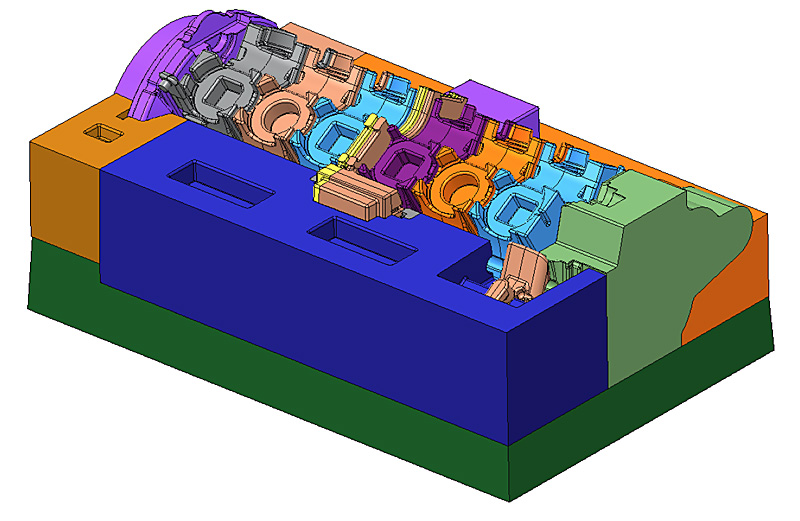 |
| The dark green core on the nearside completes the formation of the outer wall of the block. The 'U' shaped cut-outs form strengthening lugs along the side of the block. The small pink core at the front will make the mounting tower for the nearside distributor. | 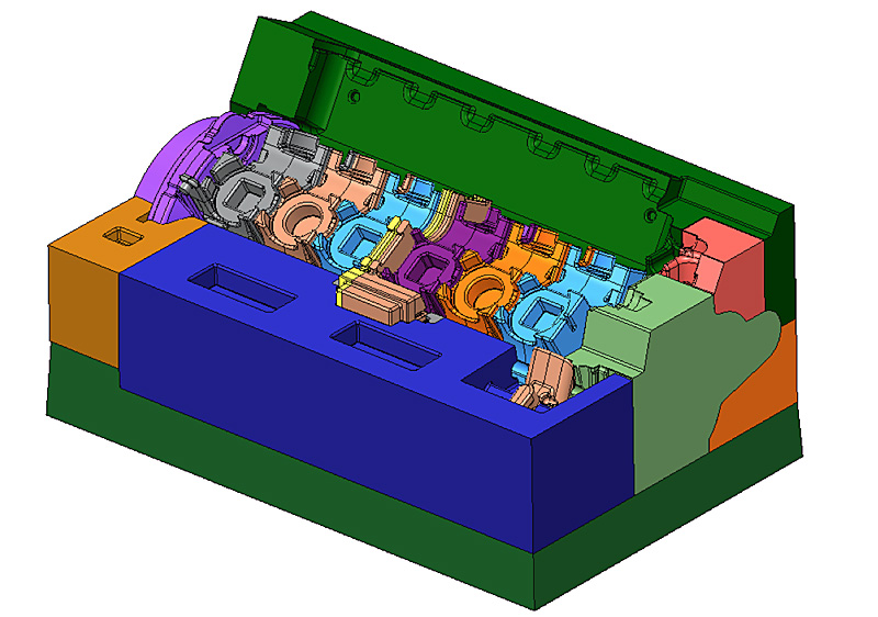 |
| The upper offside wall is created by this core. Hidden from view is the former for the offside distributor tower. | 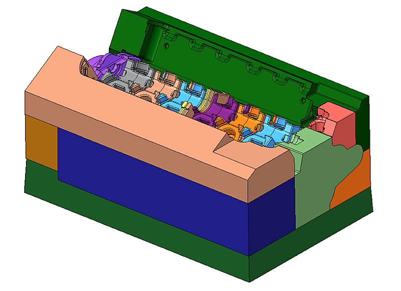 |
| The upper cylinder cores are formed in four groups of three.
As this is a wet-liner engine the cavities will provide the bottom wall of the water gallery, upper support webs, upper and lower support points for the cylinder liners and the underside of the fire faces on each bank. (Fire faces = mating faces for the cylinder heads.) |
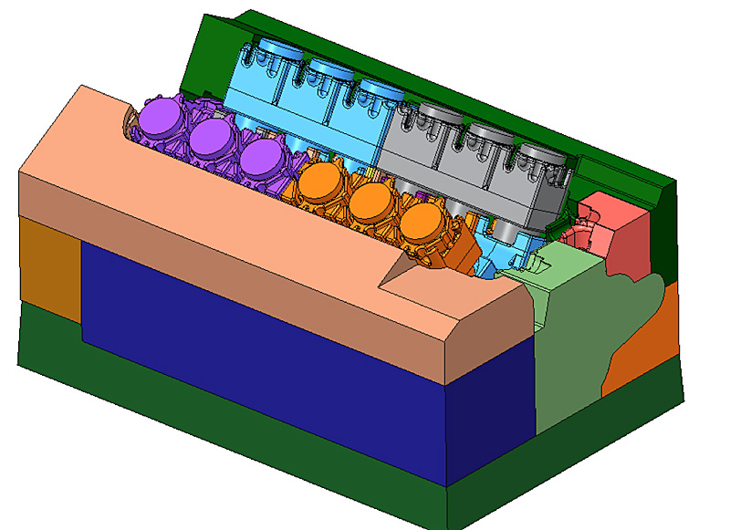 |
| The 'cope' or lid to the core box. This performs the locking function for the pack as well as installing the upper firing face surfaces. The grey inverted 'D' shape at the front is the core that provides the shape of the camshaft wells, cam bearing bridges and the cross-shaft housing for the distributor and oil pump drives. | 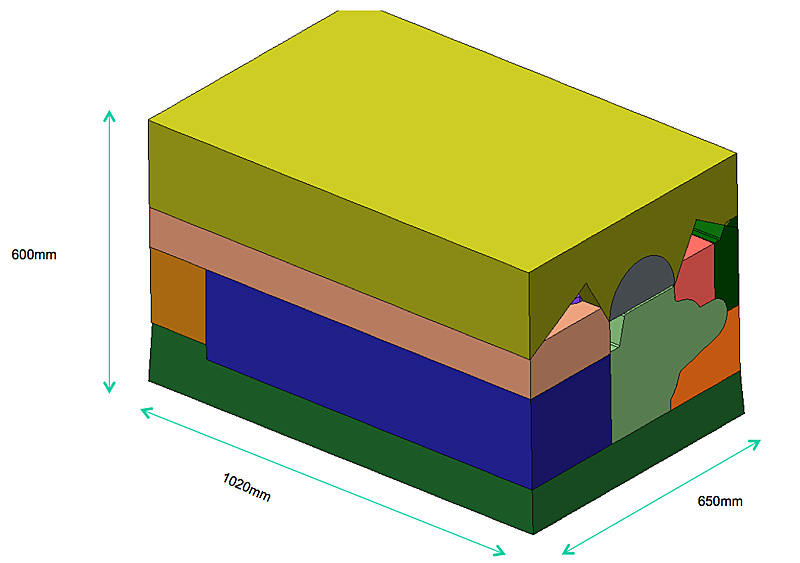 |
© Copyright 2011-2015: Phantom Engineering Limited.